Already good while ago I bought this MMC2IEC kit from Retro-Donald together with other junk. Basically it is just one hardware design variant that runs the popular and widely used sd2iec firmware. Just like the uIEC, SD2IEC, C64SD and many other devices. If you randomly come by an SD card drive for 8-bit Commodores, it’s probably some sort of SD2IEC/MMC2IEC variant.
This particular variant of the hardware goes by name Peter Sieg Platine, Peter Sieg plate. It’s Lars P. hardware configuration – which is important information when flashing or updating the AVR firmware. The kit came with ATMega 1284 AVR – a 128k chip that is likely to fit also the upcoming updates of sd2iec firmware in future.
Anyhow, this one was not a complete ready to use device, but a DIY kit that consists of nothing but the board, the SD card slot and an optional preprogrammed AVR chip. The kit with programmed AVR didn’t cost very much, and the remaining electric components were only few euros from a local electrics shop.
Even though this kit is no longer available from Retro-Donald’s Sinchai shop, I’ll go ahead and run down what I did with mine and how I built it. After all, this device is so simple, that it would be fairly easy to build one without any kit. If you have the possibility to make the PCB and program the AVR, plus solder all the parts together, you can basically make this very device from scratch.
The PCB design and layout files are also available in different formats here and on the author’s page.
Quick review
The PCB design is not quite as elegant as uIEC’s. All the traces on the PCB are rather thin, also the ones that carry power. And also the ground traces are thin lines instead of the usual large areas found in most PCB designs. The design is not very compact either, but this is mostly due to the large 40-pin AVR chip used. Anyhow the board works just fine, and spacious design makes it easier to work with the soldering iron.
As said, the functionality is identical to uIEC running the same firmware. In these two board designs there are few differences however. One major advantage of this MMC2IEC design is that the device number is configured via jumpers. It makes a device number switch possible in embedded application for example. But that’s about the only advantage compared to uEIC design-vice. Other aspects, mainly size and connectivity, fall short compared to the uIEC. Something tells me this board was deliberately designed to be installed inside the machine case – or any case with some connectors.
Summary, P.Sieg MMC2IEC compared to the uIEC/SD
Pros:
- Device number configured with jumpers
- DIY-friendly
Cons:
- Bigger
- No standard way of connecting it
The design that Sinchai.de is currently selling seems more practical. By the looks of it, it plugs into tape port (for power), has an integrated serial cable, and has dip switches for device ID configuration and a reset button. A ready to use unit that is – once built.
Assembly
The parts list and other info on this board design can be found on this C64-Wiki.de page. If you’re struggling with German language, Google Translate is your friend.
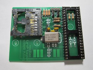
First off, this is the top side of the bare PCB, with my ugly fingerprints. Otherwise clean and tidy.
I started off by soldering the SMD parts. The SD card slot was included in the kit, and was surprisingly easy to solder in. Normally the slot would be the only SMD part, but I had to replace the specified voltage regulator with a SMD variant, as my local electrics shop didn’t have one with the correct casing and rating. I compared the datasheets of the specified and replacing regulator carefully to be sure about the pin arrangement. Then I did some fitting and found out that I could directly solder in the SMD regulator with only one jumper wire.
In this picture you can see where the jumper wire goes to. It’s the reference pin and connected to ground. Any other ground spot would have done just the same.
Here’s most of the board populated. Resistors and capacitors in place. I used tantalum capacitor for C4 – electrolytic counterpart would be perfectly fine too, only a little bit bigger. And with this board, the bigger size really wouldn’t be an issue. Instead of soldering the LEDs to the board, I used a header for them.
Now here’s the 8 MHz crystal. Again my supplier didn’t have the desired low profile model so I had to go with this huge one. If I had it installed pointing up, it would have been sticking up like a shiny silver middle finger. Instead I bent the legs so that it lies horizontally. Thanks to the SMD voltage regulator, the crystal can lay low with the capacitor bent to the side. Note also the header pins for the device ID jumpers.
Oo-kay, now all the electric components are in place, save for the AVR chip, and basically the unit is complete. But how do you connect this poor thing to your Commie? There’s nothing that you could use to plug it onto anything! I’m still waiting for magical wireless serial bus and power transmission!
Since I’m not going to sit and wait for that, I figured out something else. For the time being I was not going to install this board inside any of my Commodores, so I had to set up connectors for power and serial bus.
Welp, since the uIEC has a handy daughterboard for interfacing – which I already got, I didn’t want to reinvent the wheel. I made a pin header for the MMC2IEC board that is compatible with the uIEC header. In case you’re looking for uIEC header pinout, have a look on Berry de Jager’s blog.
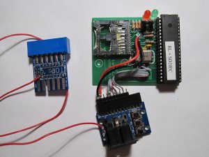
Here’s how the uIEC header looked like first. The required IEC lines (ATN, CLK, DATA + ground) and +5V are taken from the uIEC daughtercard, and two of the buttons are used as disk change buttons. Now to make this thing fly, I only need to connect a serial cable to the serial port of the uIEC daughtercard, and plug the ‘C2N Power‘ end of the red wire to the tape port for power.
But I wasn’t completely satisfied yet, as there was no reset in this setup. The solution was rather straight-forward, I used the third button to trigger the reset pin of the AVR chip. In addition to that, I added a diode to the header so that this device listens also the IEC reset line, as adviced by Unseen.
This way the device works so that it resets whenever there is active reset signal in the serial bus, just like any ordinary drive. On the other hand using the reset button on the daughterboard will not reset any other devices in the bus. This is nice as having reset makes much sense. Resetting makes the device return to root folder, become responsive again if in unresponsive state, and refreshes the device ID set via jumpers.
Here’s the setup with 100% more reset.
Also from the underside. Diode position drawn on the picture, and note how I’ve put some tube around it to prevent any unwanted shorts. The grey dashed line is just to illustrate that the reset wire just loops around the other side of the board. The leftmost (connected) header pin is wired directly to the AVR pin 9.
Finally here’s a mashup picture illustrating how I wired up this thing. Ground, +5V DC and the three serial lines ATN, DATA and CLK are connected to the corresponding connection points at the MMC2IEC board. The daughtercard buttons S1 and S2 are wired as sd2iec disk change buttons so that they connect the disk change signal lines to the common ground when pressed. The S3 button is wired directly to AVR pin 9 via the header. The diode connects the serial reset line to the reset pin as described above.
There you have it! The difference in size and elegance is notable, but both of these devices works just the same. I can tell this with confidence as I’ve been using this Frankenstein for my random sd2iec’ing for about a year already!


