A while ago I made a proper SCART cable for Amiga, so why not for C64 as well? So what I did was a C64 SCART cable with selectable composite/S-Video mode, including a ‘chroma fix’ and audio noise reduction ‘mod’ plus a preparation for possible stereo audio use. But let’s start with the theory.
Cable making principle
Building an A/V cable for C64 is not very difficult. In the simplest form, what is needed are plug for the C64 Video port, a cable with enough wires for the desired operation and the output connector(s).
C64 Video port
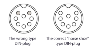
The C64 Video port is an 8-pin DIN connector, which is a standard multi purpose connector. It means that the required DIN plugs are easy to find and cheap. However, there are two different versions of the 8-pin DIN plug. The two versions differ in the shape of the arc that the pins form. Best shown as a picture:
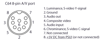
The two pins marked in grey in the wrong type DIN plug will prevent the plug from being inserted into C64 A/V jack. But not to worry in case you’re holding the wrong type of plug in your hand, these two pins can be cut off or pulled out from the connector plug. In any ordinary A/V cable they are not needed anyway. Here is the Video port pinout:
Some early C64s had a 5-pin Video port that are missing the pins 6-8. It means there’s not separate chroma signal available there. In other words: no S-Video, only composite available via the video port.
Make note on the pin 8. It is either directly wired to the +5V DC line from the PSU (after the power switch) or not connected. According to my first hand research, the +5V DC line is present in the C64 Video port in all but the earliest two models. The +5V line is present starting from model C64B, or motherboard ASSY-NO. 250425. That means machines manufactured starting from 1984.
If we are looking at the numbers in this fascinating research of the number of manufactured Commodore 64s, we can assume that roughly 70% of Commodore 64s have the power line at Video port. And those are the latter 70%, meaning they are likely in the majority of C64s still existing and in operating condition.
This is noteworthy as many sources on the internet claims that the +5V line is present only in the later C64 C models and in C128. The motherboard version C64B / 250425 that introduced this feature is used in old style ‘breadbin’ models in great numbers. All C64 C models have motherboard model C64B or later.
To sum up;
| C64 model | Motherboard ASSY-NO |
+5V DC on pin 8 of Video port |
| C64 | 326298 | no* |
| C64A | 250407 | no |
| C64B | 250425 | yes |
| C64B3 | 250466 | yes |
| C64E | 250469 | yes |
I have C64s of different models, including C64A, C64B, C64B3 and C64E. The above is based on measurements and examination of the motherboards I have. The earliest model ASSY-NO 326298 I do not have, thus I’m not able to verify the case with it – *it’s an assumption.
And in fact, the first models probably all have the 5-pin video port, and thus, missing the pin 8 altogether.
I think that’s enough for the A/V port itself.
A/V Connectors, number of wires etc.
The signals from the C64 Video port are then carried to suitable connectors that plugs into TV or monitor. The options for number and type of connectors are many. The A/V port gives composite video and separate luma and chroma, which is essentially S-Video (well, kind of, see MiaM’s post on the comments). For composite video, only a single male RCA plug is needed. For separate luma and chroma, two RCA plugs are needed. This kind of connection can be used with e.g. Commodore video monitors that have these inputs for best possible picture quality. Many televisions still support the separated luma and chroma in the form of S-Video, and the commonly used connector for that is a 4-pin mini-DIN plug.
The C64 outputs only mono audio (unless modified with second SID chip), so one male RCA plug for the mono audio is enough. However, many TVs don’t understand mono audio input as such, and you would be hearing the audio only from left (or right) speaker if connected with only one plug. Therefore it might be useful to double the audio output for both left and right channels.
Alternatively all the signals can be wired to a SCART connector. That’s what I did.
Talking about SCART, please note that SCART is not a video signal standard, it is a connector standard. A SCART lead can carry video in different formats plus audio – just like the modern equivalent HDMI. So when talking about SCART cable, it should be mentioned which signal type is being used, only referring to SCART alone does not necessarily mean anything. According to the standard, a SCART connection can carry composite, S-Video and RGB video signal. A C64 outputs both composite and S-Video, but not RGB.
Finally between the 8-pin DIN plug at the C64 end and the chosen connectors at the TV/monitor end there should be adequate length of good quality signal cable with enough wires. Just count the number of signals desired, and add one for ground.
For a composite video + mono audio cable, two signal wires + ground wire is enough. For the cable I made, I used a six wire shielded signal cable. That’s luma, chroma, composite, two wires reserved for audio and a ground wire.
Building up the cable
This is how I made my cable. I’m not going to make a step by step instructions, the information given and the diagram below should be more than enough for a nifty DIY person!
Update: I made another post with step-by-step instructions – and this time without using the SCART plug.
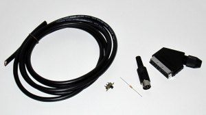
These are the ingredients. Six wire shielded cable, a switch, 330 ohm resistor, 8-pin DIN plug, a SCART plug.
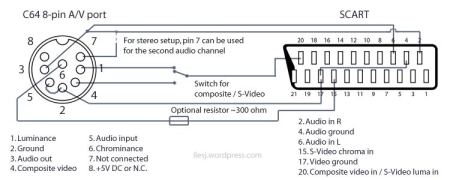
And this is the diagram of the cable I made for myself, provided as post-production!
The SCART connection can carry several different video signals, but composite video and S-Video share the pin 20. Therefore a switch is needed to select between them. If only S-Video is desired, the switch and connection to DIN plug pin 4 can be omitted. In case of composite only, the connection to DIN plug pins 1 and 6 and the switch can be omitted.
The resistor in chroma line is an attempt to improve picture on modern TVs. On some TVs there’s a distinctive checkerboard pattern visible when using an S-Video cable with the C64. Apparently this is because of too strong chroma signal. Or that’s what teh internets told me, it could well be something else. Other possible symptom is the colours going mad. On both of our household TVs I get the checkerboard pattern, so I installed a 330 ohm resistor to the chroma line. Some fellow Commodorists have reported getting rid of the pattern that way. Sadly, the resistor didn’t make great difference with our TVs. Seems I have to try out different values, or some other means. Anyway, the resistor does not do any harm, and if it improves the picture on your setup – good for you!
The noise reduction mod, or feature of cable, is the simplest modification ever. I simply joined the DIN plug pins 2 and 5 with a bent piece of wire. This connects the audio input to ground at the Video port, reducing noise that the audio input picks up. This is because the audio in line is left floating on the C64, and that way it works like an antenna picking up all kinds of noisy mess from surrounding electrical fuzz.
Connecting the audio in -pin to ground is perfectly fine (unlike grounding the audio in pin of the actual SID chip!), the only thing you loose is the possibility to feed external audio to SID. I would not recommend that in any case anyway – it’s an easy way to bust the SID chip. The best use for the audio input is to use it for noise reduction.
But don’t get too excited. The noise reduction mod won’t do miracles alone and make the C64 free from background noise. Especially the VIC-II and video circuitry will still make noticeable noise that you can hear from the audio output. You might have noticed that the level of the characteristic audio background buzz is related to what happens on the screen. At best this mod reduces the level of that noise significantly. Getting rid of all noise calls for some other means, as it’s even possible to playback audio without using SID chip at all! One part in Vicious SID plays audio using the video circuitry. I’ve tried it with SID chip removed – and yes, the chords in that part could be heard. That’s how much there is interference in the different signals inside the C64.
Both the S-Video and the noise reduction mod among many others are described in detail at C64 AlphA MOD page.
By the way, an S-Video SCART cable can actually work with receiver that supports only composite video in the SCART input. This is because the composite video is ‘backwards compatible’ with black and white video signal. If the luma signal is fed to composite input, the result should be black and white picture, and that’s how it’s supposed to be. The interesting thing with C64 is that the picture will most likely not be black and white, but a colour picture! This happens because the rather poor video circuitry leaks the color information to the luminance signal. The TV picks up the more or less weak colour signal, and thinks it’s composite video after all. What happens then is up to the TV/monitor. Some TVs can amplify the colour signal way too much resulting in complete colour chaos. Other TVs may show perfectly fine colour picture.
So in a way, the C64 S-Video SCART cable can be “auto sensing” and work in composite TV set anyway, as seen pictures further down. The picture quality will somewhat suffer of course.
Building tips
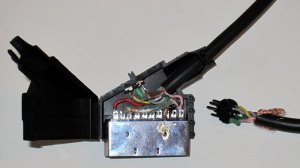
Here you can see how I mounted the switch. The red wire will go to SCART pin 20. Composite and S-Video signals will be connected to the switch terminals. The wire inside SCART plug connects video and audio grounds, SCART pins 17 and 4.
Stripped wires prepared. Note the plug covers on the cable. They’d better be sneaked on the cable before soldering the connectors in.
The plugs before closing them. The cable shielding is connected to the plug bodies, ground line runs separately. The resistor resides inside a piece of clear heat shrinking tube to prevent any shorts. The cable becomes a stereo cable simply by detaching the pink wire from the DIN plug pin 3, and connecting it to pin 7. Then, also a switch for stereo/mono could be mounted to the SCART plug.
Picture time!
Some examples how picture look using the cable, with both composite and S-Video signal. Once again, big pictures unmodified from camera.
Panasonic plasma, composite left, S-Video right:
Samsung LCD
Philips CM8833 CRT. On left: composite. On right: luminance only! As you see, the picture is not black and white. Chroma leak is real, man!


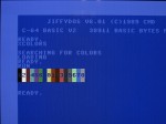

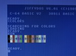
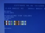
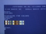
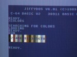

AFAIK the picture quality improved a lot on later C64’s, perhaps the circuit boards got redrawn in a better way.
Notice that you get a darker shadow on the right of color 6 (on Samsung S-video). That is because the C64 doesn’t really output a normal S-video signal. S-video were not commonly used when the C64 was new, so therefore there were no real standard for such signal in consumer electronics. The output from C64 has a different luma-chroma-timing than standard S-video.
If you have an old CRT TV that has for example TDA4546 as delay line (combined with CTI) then it’s possible to select different delays and find one that suits C64’s output better.
I’ve modified my old CRT TV in this way when I added a S-video input. It has a thumb wheel with 8 active positions that selects the delay used in s-video mode. :)
Hey, thanks for the informative comment!
Yes, generally newer C64s have better picture than older ones. The VIC-II chip had several different versions and revisions, and it probably got better over time. Especially the early VIC-II chips are said to make rather poor video signal. It’s no wonder if the VIC-II got better with later revisons, and especially the HMOS version used in late cost reduced C64E boards produce much sharper picture.
Also the RF-modulator plays a big role in the picture quality of C64. It is part of the video circuitry, and the final Y/C and composite signals are generated in the modulator. Also the modulators have been revisioned over time. I guess some models are better than others.
You are absolutely right in that the C64 does not technically output S-Video, for the reasons you mention, but rather separate (well they aren’t completely separate in reality but..) luma and chroma in a C64 specific mix.
I recently read a post by Bil Herd where he mentions this signal delay. He also mentions that the Commodore monitors were tweaked for the C64’s signal, and thus, “CBM signals look best on a properly matched era CBM monitor”. So it sounds like your TV mod is very clever one :) I guess the delay could be also tweaked at the C64 side for modern TV compatibility…
is it possible to build a cable with hdmi?
@iva, no, not possible like this. HDMI is a digital AV interface, and with C64 we have analog video signals. Turning analog video into digital would require some complex signal processing. There are video converters for this.
SCART? Why… ;”’-(
You can build the cable using what ever connectors suits you best.
Because there are actually people living outside the US, for example in Europe :P
Is there connection pin5 to pin2 ? yes, handwrite.
Yes, there is connection between pins 2 and 5 in the DIN plug. This simple jump wire connects AV port’s audio in pin to ground. The result is reduced background noise.
Works great, thank you.
But I want to use a converter from Scart to HDMI. The converter works just fine with my PS2 and my GameCube. The C64 cable shows from time to time a picture. The duration without image and also the duration of image are random.
SCART = horror
Again, SCART is just one option for the TV/monitor side connection. If you are building a cable for yourself, you can choose whatever connector types suit you the best.
[…] TV / Monitor to C64 – Theory: https://ilesj.wordpress.com/2012/03/30/c64-av-cable-theory-and-practice/ – Buying: http://www.amibay.com/showthread.php?t=30409 – […]
Stupid question… For the stereo setup, don’t understand exactly how the pin 3 + pin 7 (which in theory is NC) works… Is this supposed to be just to simplify soldering or something instead of soldering 2 cables to pin 3 or what? (And if so, isn’t the pink cable that is mentioned still a second cable soldered to pin 3?).
Hi Walter,
The C64 only has a mono audio. But in practice all televisions (or audio amplifiers) have stereo input. That’s why we want to connect both the left and right audio channels. Otherwise we would hear the C64 sound only from the left or right speaker.
So in the cable, both the left and right audio wires are connected to the DIN plug pin 3, audio out. We can call this ‘dual mono’ – same sound from both left and right speaker.
And correct, the C64 Video port pin 7 is not connected.
However, it is possible to modify the C64 to have a second SID chip.
Normally there is no output for second audio channel in the C64. So the audio from the second SID chip can be carried over the pin 7, which is otherwise unused.
I hope this clarifies!
Hello,
first I’d like to thank You for that very nicely written article. It helped me alot while I was crafting my own video cable. I made two cables – one composite and the other one s-video.
From my experience:
At start I was sitting on “antena” cable (good colors – but bad quality of picture). Then i made an composite cable – good colors – better picture quality but still not much different then antena cable. After that i made an s-video version – very nice picture quality, clear pixels but colors are messed up :( I can clearly see some red and green in places where it shouldnt be. Im afraid im experiencing “…TVs can amplify the colour signal way too much resulting in complete colour chaos…” its not that bad overall, but you can clearly see the difference for example when looking at pure white text on antena cable and then switching to s-video cable you can clearly see the text is not pure white anymore is more like white with some red and green in it. I tried with and without 300 ohm resistor (cant see any difference).
I really like the picture quality that s-video cable provides. Is there anything i can do, besides swapping my TV for something else? Btw im using an old Sony KV-14M1K CRT TV. Thanks in advance for Your time!
Hi! Did you make the S-Video cable using a SCART connector? I’m replying now assuming you did.
Check that your TV is really receiving the S-Video signal. Many TVs have two SCART sockets, and only one of them is compatible with S-Video signal. And often TVs won’t auto detect S-Video over SCART and default to composite. So you may have to manually choose between S-Video or composite over that AV input with some input setting or selection.
What you describe sounds very much like S-Video signal fed into composite input; the picture is sharper than composite, but colors are way off and messy. Reason for that behavior is that composite and S-Video signals are carried over using the same pins on SCART connector. S-Video luminance signal that includes some leaked and weak color signal is then treated like a composite signal by the TV.
Ha, ha, ha :D. Funny How many answers this got (in this day and age). I too made a cable (cause back in the days I used only the coaxial cable (RF port) and the picture was bad and it influenced sound – especially when using yellow letters – I remember – noisy as hell :D). Yesterday I got around to try to make a cable – just for laughs. Previously I bought DIN, 6-wire cable with shielding and SCART to construct it, but then I figured – I’m not gonna use SCART – I have a camera cable with three part audio jack and separate composite and audio plugs on the other side – that’s far more practical. Cable constructed – so now I have DIN on one side and two audio jacks on the other – one for AV and the other for Audio-IN – which of course begged a question – would I burn the chip if I plugged in microphone or line (from MP3 player for example) – actually what can we plug in the AUDIO-IN – what is it meant for originally, what is it used for?
I found this post because I was kinda wondering if I made my cable correctly and if there is the best way … and now I see that this falsely named “Luminance” output gives out far sharper picture :D , darn it. …Maybe I’ll switch it. Or – can both be on the same wire?
To anyone asking about the AUDIO IN on the AV port, my advice is: Unless you’re absolutely sure what you’re doing – DON’T DO IT!
Would you burn the chip? If you are not 100% sure about the accepted voltage levels etc, it’s better not to try your luck. You just might burn the chip, yes. Many have. That is a valid concern.
Luminance signal is just what it says. Except that in case of C64, the color encoding signal tends to leak into it. I’m not sure what you’re asking exactly, but if you’re planning to use this luminance signal for composite input or jack, you would probably get a sharper picture, but with bad colors. Connecting the different signal options together doesn’t sound like a good plan.
I was thinking of hooking my C64 up to a VGA-monitor using a “homemade” C64-to-S-Video-cable and then a Video-to-VGA-converter and finally VGA-cable to the monitor. Do you see any problems or issues with this setup? I only have 50″ plasma otherwise, I can’t imagine that will look good… I was thinking a 17 or 19″ VGA monitor.
On principal level I don’t see any issues. Just don’t expect stunning image quality using that setup either.
Picture will more or less suffer from the video conversion process – unless you are using professional video signal processors for the job.
Definitely worth a try to see if the picture looks fine on the monitor. Also worth trying how your TV handles the un-converted S-Video (if there’s an input available). At least the pixels will be large :)
No S-video input on the 50″ I’m afraid. SCART with possible S-video support, but then I need another cable :)
I just got everything hooked up, but the picture is horrible on the VGA-monitor. flickering and basically black and white. :( the s-video cable works if I hook it up to my “new” TV. So it’s either the converter or the monitor. Got any suggestions?
Ben: be sure to select s-video and not composite, otherwise it will look like you explain. If you don’t have any such setting then you’ll probably have to use composite video (another pin on the C64).
Hi there, I made the scart cable, and it works great thanks!
But could you or somebody else help me to make composite cable (RCA): I made a cable which has pin 4 connected to RCA tip and pin 3 (ground) connected to the RCA sleeve. Picture comes, but right away it starts to scroll down.
I’d like to connect C64 to car monitor (PAL/NTSC).
best,
Jose
Actually, I tried the composite cable on modern LCD TV, and it works allright. The pic is still and ok.
The 3,5″ car monitor I’m trying to make make work is cheap thing from China. Is this mission impossible?
best,
Jose
Hello there,
Umm… Pin 3 is not ground but audio out! That’s my first suspect for the fault. Pin 2 is the ground, right next to the composite video, pin 4. Let’s hope your SID chip hasn’t been damaged.
EDIT: Replying also to your second comment – In case the pin numbers you wrote were a typo, and your cable is ok (please do check & verify that first), it can be that the Chinese car monitor doesn’t simply work with C64’s signal.
Thanks for replying! Yes it’s on the right pin(2), I just remembered the number wrong. Sorry.
Maybe the car monitor wont work then. Would someone recommend me a slim and tiny LCD monitor w/ S-video connection, which could work w/ C64.
Thank you for this awesome guide!
A friend made a similar composite cable for his C64, but there is one thing I noticed, and it’s not a problem more of an observation… the sound via an RF connection sounds sharper and more defined than via composite. It’s not much but it is there, and the colours are sharper in RF
Also could I ask do you know if the games were made for an RF connection in mind or composite? Also when the C64 came out was RF more common than composite?
Thank you :)
That’s interesting. Haven’t noticed anything like that myself. If the modulator is good (they vary between different models) and well adjusted, plus the television has an excellent analog tuner and the channel is precisely tuned, the picture and sound can be quite good over RF. And similarly, the handling of composite signal vary between televisions. In theory composite should be better in quality than RF. And sound is carried as direct line level signal if taken from the A/V port. If carried over RF, the sound is being modulated and demodulated for the transmission.
RF was likely the most common way to connect the C64 to TV back in the day. But also better options than composite were available. For example if using Commodore monitor and a cable with separate luma and chroma plugs (basically S-Video) the picture is very sharp. But I’m assuming most users were using only the provided RF lead with a TV set.
It’s well possible that some game developers took some advantage of the inherent blur of RF or composite signal. Can’t name any particular title though. If someone can name examples, please comment! :)
Well, I have two different C-64 AV to SCART connectors going from my C-64 to a Samsung multi-sync TV. In one of them, the checkerboard pattern is absolutely horrendous, some color combinations are practically illegible. With the other cable, the checkerboard pattern is gone, the text is clear in that regard…. but the colors are insane, way over-saturated, splotchy colors everywhere and even vertical “bands” of alternating color hues.
Uggg. Both these cables were bought online, I don’t know if a resistor was used in either without breaking into the cables.
I suspect one does, and one doesn’t. Unfortunately the picture quality on either is terrible.
Guess I’ll have to find out and see if I can modify them accordingly.
,
Well, I opened the SCART connectors. Neither has the resistor on the Chroma line. Seems like they cheaped out. So I know what I need to try first and that’s installing the resistor.
Would be interesting to know if you manage to modify the cable for better picture, so please post back if you’re successful! Also, are these cables wired to carry S-Video or composite video? SCART connector can carry both, but only one of them can be wired at a time (if not using a switch like I did).
One note regarding resistors in the chroma line; those can be easily fitted into the DIN plug end of the cable too, and I think it may actually be the better choice. To really know how the cables are wired, you need to open both ends of the cable, or examine how the pins are connected using a multimeter.
Interesting point. There’s also the issue that the TV may not support S-Video on the SCART connector at all. I posted a picture on Lemon-64.com and a general consensus was that my TV was displaying Luminance with a bit of Chroma bleed, and was not trying to display S-video at all. So I may be stuck with Composite only as my best option.
In theory it would be best to place the resistor at the DIN end if the cable actually has 75 ohm impedance. However cheaper cables are probably not 75 ohm. Also the luma-chroma timing difference between C64 and standard S-video can also play tricks here; an “incorrect” resistor placement might skew the signal so the timing is improved (or might get worse…). Experiment! :)
Nice!!!! Thank you
[…] Diagramma scart per cavo DIN 8 pin per C64, foto rubata a Ilesj’s Blog […]
Hi,the cable used have a 5 or 6 wire?
Hi, well it depends on what kind of cable you’re making. I would recommend S-Video cable – if your display supports that. For a “normal” S-Video cable you need only 4 wires: mono audio + luma + chroma + ground.
So 5 wires should be enough.
The cable I’ve made as an example in this article has six wires. That’s because it is switchable between S-Video / composite, and has an extra audio wire for stereo audio (dual SID) possibility.
Please read through the chapter A/V Connectors, number of wires etc.
Hi. im having trouble hooking up my C64 (breadbin and Cs) to my Sony bvm-20e1e. It has one set of RGB BNC connectors and a separate card that accepts composite and RGB (without sync?) I have no problem with my Amiga or Spectrums video to RGB scart but the C64 posses a unique problem. Im not sure if its better to go the S video to RGB conversion route or to use the separate card and go with composite? I always heard that svideo was superior to composite but after reading your article and looking at the screenshots im not too sure? Any ideas on how to hook up a C64 to a broadcast quality monitor to get the best possible picture?
Cheers
Hi! If you’re after the best picture quality, you’ll want S-Video. It is much sharper than composite video. The downside of the S-Video from C64 is that it does not hide the C64 video imperfections such as stripes across the screen so well as more blurry composite… The C64’s S-Video produces often some checkerboard pattern, but it can well be that your professional monitor can handle the signals better than consumer televisions. And it’s hardly an issue compared to the overall jaggieness of composite. Check the vertical edges of the color bar pictures for example.
If your BVM monitor does not have an Y/C input, then, in theory, you should get best results with a good S-Video to RGB or S-Video to component (Y Y-B Y-R) converter.
I briefly checked BVM manual and some of the interface cards take S-Video (Y/C) directly. If I read the spec sheet correct, what you’d need would be a BKM-24 or BKM-25 card depending whether you live in NTSC or PAL land, or BKM-27 tri-standard decoder.
I hope this helps!
Hello ilesj. Thanks for the reply. The card I have is the BKM-21D which doesn’t have s-video I think? Instead of buying a BKM-25 (i’m in Pal land :)). I think I might have to go the S-video to RGB route. Even though these little devices can be quite expensive too. Do you know if there’s any lag or other unwanted effects when converting S-Video to RGB?
Cheers
Trydowave:
It might be possible to modify your composite/PAL input board to take S-video. I did that modification to my CRT TV some 10-15 years ago. I used the scematics for a similar model with säS-video input as a guide/hint/help to figure out how to do it.
Its ok :) Id probably end up busting it if I attempted that. My soldering skills are dire. I tried to fix a 1541s pcb and killed it. Ended up replacing the whole pcb instead. Ill go the s video – rgb route. It means I can hook it all up to the same bnc ports via a scart splitter. cheers
Trydowave, about that lag; it depends a lot on the converting device. If it’s an analog transcoder, it will introduce a small delay into the signal path, but it’s so small it’s practically nonexistent.
If the converter does some other stuff, like converts the signal to digital format, or does some deinterlacing or upscaling, it will create a lag of at least one frame or more. But you shouldn’t need any of those tricks with your monitor :)
I’ve never used any of those cheap S-Video to something -converters, but I’ve understood that the quality of the converted image is not always… let’s say flawless. As you say, the ones that does the job well come with a price tag.
Hi. Not related to the above subject as such but Id though id ask you anyway (Your Extensive knowledge an all :)) . Recently brought 2 way BNC splitters so I didn’t have to switch my VGA to BNC and Scart to BNC connectors (The BVM only has one RGB input with sync).
Problem is the connection is very iffy. Sometimes it doesn’t work at all, where sometimes it close, but with a pink tint? This happens no matter what I try. I was just wondering why something as simple as this splitter doesn’t seem to work?
The splitters look like this: http://www.ebay.co.uk/itm/like/150879222558?adgroupid=13585920426&hlpht=true&hlpv=2&rlsatarget=pla-131843273586&adtype=pla&ff3=1&lpid=122&poi=&ul_noapp=true&limghlpsr=true&ff19=0&googleloc=9045052&device=c&chn=ps&campaignid=207297426&crdt=0&ff12=67&ff11=ICEP3.0.0-L&ff14=122&viphx=1&ops=true&ff13=80
Cheers
So you have two machines connected to one video input using these BNC splitters if I understand correct. I would think that the other machine (which is not being used at the time) is not a proper termination for the BNC cable. So the signals kind of “leak” and get messed up. The pink tint sounds like something you might get if your green video component is missing part of its strength.
I stopped using video splitters after I noticed this: I had Playstation and Saturn connected in a SCART splitter, and whenever the PS was on, the power LED of Saturn would light up, even if it wasn’t plugged into power outlet at all. Splitters just connect stuff together. Whether they are meant to be connected together or not (like Saturn’s and PS’s video ports probably aren’t meant to be connected to each other).
How about SCART or VGA switch instead of splitting the BNC connections?
I made sure not to have both devices on when connecting the splitters. The same thing you mentioned happened to me in the past. I was just seeing if one device hooked up through the splitter (with the other end unplugged) would display the same crisp and clear picture. It didn’t and on top of the that a slight jiggle of the splitter would disturb the picture, like it was a loose connection. Basically there completely unusable.
There was only one reason why I needed the Splitters. My Amigas, Spectrum and any other scart device would go through the scart splitter then from there to BNC. The only thing not going that route was the PC (emulations) VGA to BNC.
On a forum some guy said I had to buy VGA to BNC because VGA to Scart wouldn’t work? Something about missing the Sync? Im not sure if this is correct though. Getting the PC to go from VGA to Scart then to the Splitter to BNC would sort out all my problems.
http://www.ebay.co.uk/itm/SCART-Cable-to-SVGA-VGA-15-PIN-HD-PLUG-Lead-1-5M-UK-/361224212922
Not getting this one, Just an example. And ive noticed that it says that it wont work form PC to TV. I think the Graphics card has to putting at the correct Res, to 15hz monitor etc otherwise a convertor box is necessary (which I want to avoid.)
I don’t think im ever going to get this thing to work.. really complicated.
This is how far ive got with mame so far on this monitor:
Can’t for the life of me work out how to get the correct aspect ratio or frame rate. I think they all have to be set up manually or with other software.
Sorry.. gone off topic there a bit :)
Just another idea. Bit of a Frankenstein job :) This would be cheaper for me as I have most of the stuff already lying around and it might take care of the sync issue.
What about VGA to BNC, BNC to BNC male to male adapters, BNC to RGB to female scart, Male scart to Scart splitter and finally Scart to BNC.
Would that work?
Adapters: http://www.ebay.co.uk/itm/10X-BNC-to-BNC-Coupler-Cable-Connector-Adapter-for-CCTV-Cameras-Security-System-/131505540278?hash=item1e9e574cb6:g:ROwAAOSwPhdVStTJ
To my understanding, a coaxial BNC cable should be terminated properly (i.e. not left open, either). The idea is that the signal wire runs encapsulated between devices, that makes the signal more resistant to interference. That is why such cables are used in broadcast equipment. Now if you have the BNC splitters, they also split the signal wire, and the signal runs all the way to the other console/computer, no matter if it’s turned on or not. And that is not a proper way to terminate a coaxial cable. My example with the power LED was to say that splitters interconnect the devices connected to splitters.
Whether VGA to SCART works or not depends on several things. In most cases it won’t, because TVs (usually) expect 15 kHz signal from the SCART port, but computers (usually) give 31 kHz signal. Another difference is that VGA connection has horizontal and vertical sync pulses running on dedicated wires (often referred as RGBHV), but SCART (and TVs using it) only supports combined sync (CSYNC, RGBs). H and V sync signals can be combined into CSYNC within the cable, and that’s ok with SCART.
But! If you have a VGA to BNC cable that works, I see no reason why you could not use VGA to SCART cable instead. See, the signals don’t care what kind of connectors are used to carry them, as long as they are connected right. It works if your monitor supports 31 KHz signal. If VGA to BNC cable works as such, it does. Why VGA to SCART does not work on TVs, is that TVs don’t support 31 kHz signal.
Your Frankenstein might work, but keep in mind that every added connector is a potential fault or misconnection in the signal path. Also risk of wrong connections increase.
You got a quality monitor, why not consider using proper cables with it. Check for example retrogamingcables.co.uk – I’m sure there’s a solution for you.
And don’t use splitters, prefer switches instead (a switch disconnects all other inputs, only the selected one gets connected).
Cheers!
Hi. Thanks for the response. I got quite a lot working with it the other night. Got the PC running through it at 15hz (in software) using a Radeon 9250. Frame rates great and image is displaying correctly. But it was still attached to the only connectors with a sync. I tried plugging my Amiga into the BKM-21D via the bottom RGB ports (minus the sync). The A500 picture was great apart from a flicker and there was no sign of sync problems. Turned on manual brightness and the flickering went away. In set up for SDI card was an option called sync Int or Ext. I choose Int and this seemed to get rid of the sync problem. Thought all my problems were solved but when I plugged my A2100 into the same connectors as my A500 the picture had moved to the right slightly and sync was an issue again. This makes no sense too me. But.. its not too important.. as I can get the A500 in its ok…
Now.. onto what I was originally talking about. The C64. for fun I tried plugging in the yellow cable (sync or composite) to the the green composite connector on the BKM-21D. I got a picture but it was terrible. all blurry and faded.
But. I did notice something on the front of the BVM. Its a little port called an OPTION connector. It looks like and s video connector but with 7 pin holes? Not sure what it does but it would be great if it was s video!
Cant seem to post an image of it here. U can see what it looks like on this thread that I started…
http://eab.abime.net/showthread.php?t=81125
OPTION connector: “Used to connect the BKM-11R Monitor Control Unit or BKM-14L Auto Setup Probe.”
Reads in your monitor’s operation manual. Google for it and you’ll find it.
Nice to show the pin out. I made my video cable with Stereo out put and used the pin 7 for the 2nd SID and it’s stereo. I did that like 20 years ago now.
Is there a way to do this in reverse? There is a SCART wire for the Super Nintendo that allows you to get a much better picture than composite. I would like to be able to use it with my NTSC 1084-S monitor but the US model did not include the SCART port, although there is a blank space for it on the back of the monitor.
Thank you
Hi – there’s a way for sure, but you need to do some research.
It should be possible to modify and add the SCART socket to the monitor, but that’s not a trivial thing to do. You would need to open up the monitor, find schematic diagrams of the monitor, trace the connections on the pcb and see if there are some other components missing in addition to the connector itself.
A lot more practical thing will be to make/get an adapter cable. A cable with female SCART at one end, and suitable connector(s) wired properly at the other end, that will then plug into your 1084.
A SCART cable with “much better picture than composite” can mean either a cable wired for an RGBs signal or S-Video signal. Both signal types are supported by SCART connector and SNES. You need to know what it is you have in order to connect it to your 1084 properly.
There are several different models of 1084, but I think most of them do support S-Video and RGBs signals.
IF your SNES SCART cable is RGBs (best possible video quality), you need an adapter cable that plugs into another RGBs-compatible port that is available in your 1084. Some 1084 models have a 6-pin DIN port for analogue RGB signal, and some have a 9-pin D connector. You should be able to use either of those if present (NOT the 8-pin RGB TTL port, it won’t work).
IF you have an S-Video SCART cable, the adapter cable plugs into RCA connectors found at the back of the monitor. There should be four female RCA connectors; CVBS/LUMA (yellow), CHROMA (red), R.AUDIO (black) and L.AUDIO (white). LUMA and CHROMA are basically the same signals as used in S-Video, and can be connected accordingly from the SCART socket.
By Googling the topic, you’ll find plenty of discussions covering them on several forums.
I hope this helps!
Hi, great write up – can you explain in a bit more detail about pin 8 the +5V DC line from the PSU wiring?
Specifically – I have a later model 64c – On the motherboard video connector side, I assume 8 is hooked into the 5V PSU line.
So does that mean I should run a wire to pin 8 on the DIN to the SCART connector? If so, which pin on the SCART should this be connected to?
I bought a 8 pin DIN > SCART cable off of ebay a few weeks ago, which has the Composite S-VIDEO Switch – it also has a 330ohm resistor running on the chroma line.
Since I am in the US, I run the SCART connector to a SCART>HDMI adapter/upscaler (cheapy off of ebay) then HDMI to my Samsung T260HD LCD Monitor.
When I have the SCART cable Composite>S-video switch set to composite – the image is bright and very colorful blue when I turn on the C64c.
When I have the SCART cable Composite>S-video switch set to s-video – the image is not quite as bright and the colors a a little more dull. It also looks just a little bit like one person who commented above, where there may be just a very small bit of red/blue showing up in the white lettering displayed on screen.
I opened up the cable and by passed the OHM resister, and it darkened the signal more, so I put it back on.
I also removed the sub circuitry from the RF modulator (another little hack I found), which brightened up the s-video signal ever so slightly (didn’t see a difference when the switch was set to composite).
Lastly, I have a LumaFix64 – one of the POT’s is a Chroma adjuster – I can turn this pot when I am using S-VIDEO>SCART out and make the image turn from the dull colors to black and white. Then adjust it back to the dull colors while the C64 is on. If I take out the LumaFix64, I see no difference other than the introduction of more of the vertical lines – which is the reason I have the LumaFix64.
I’m about to start ripping open this cable and start from scratch, but wanted to share my experiences and explain what I am seeing to you to see if you have any ideas – perhaps the S-video wiring in the cable isn’t set properly?
Hi Thomas,
The +5V on C64’s AV port is not relevant here. There is absolutely no need to run the +5V line to the SCART socket. I mention the +5V DC line only because it is there. So that anyone who is tinkering with C64 video cables would understand that it’s possible to short-circuit the machine and its power supply if one is not being careful with the AV cable wirings.
I think your SCART to HDMI scaler does not support S-Video. Everything you describe points to this direction.
While SCART connector supports S-Video, not all devices do. The S-Video support over SCART has been added to the standard after the initial specification, and thus shares pins with other signal types. On SCART connector, S-Video’s luma signal (brightness, or b/w picture) is fed to same pin as composite video, hence the switch. Chroma (color information) signal is fed to analog RGB red input, and is ignored in composite video mode.
The S-Video luma signal is essentially composite video without color information. If you feed this to composite video input, you are supposed to get a black and white picture. And this is what happens, if you use S-Video SCART cable or adapter on a SCART input, that does not support, or is not set to S-Video.
BUT! With C64, you usually don’t get a black and white picture, but a picture with bad colors. This is because the C64 video circuitry leaks some of the color information to the luminance signal. Result is a sharper picture, but with bad colors compared to composite video.
This is what causes so much confusion; S-Video fed over SCART input that does not support S-Video does work – you get a picture with colors – but the colors are really weak or messy.
If a SCART device does not specifically state an S-Video support over SCART input, it is best to assume there isn’t S-Video support.
I hope this helps!
Excellent – thanks for steering me in the right direction. Very helpful. Looks like I may need to find a different converter (that supports s-video), or a monitor with s-video input and go from there. Really appreciate your insightfulness.
No problem :) For what I’ve read from others’ experiences, there are some cheap S-Video to VGA or HDMI converters that can have the job done, but the image quality is not stellar. I have understood that the best option out there is XRGB-mini Framemaister. That is a scaler dedicated to retro machines, has an S-Video input, and does great job also with C64 I’ve heard.
Heh – I’ve had my eye on the Framemeister for a bit, but I don’t think I’m ready for that big of a commitment for the C64 video solution. The SCART>HDMI converter I have works great for my Amiga’s RGB connection for now. I do have the cheapest of the cheap S-VIDEO > VGA converters where I started my C64 upscaling, but the picture was subpar – for one the cable I had was unsheilded and the device was 10 dollars. I’m in the process of buying a shielded s-video cable from cool novleties on ebay and plugging that into the cheap converter. If it’s still not to my liking I have my eye on a few different under 50 dollar solutions. I’ll get there eventually. Half the fun is learning! Have a nice soldering kit on the way in the mail as well. thanks again for your help.
My 250407 REV.B have a separate Luminance and Chrominance singals – i tested it on a Sony Cam
So do mine. Older models with 5-pin AV port do not have output for separate luma and chroma.
[…] As a reference I used Ilkka Sjöstedt post. […]
[…] It wouldn’t matter if the video quality wasn’t great. But after I made the necessary adapter cable and hooked everything up, I was a little disappointed to find out that the display wouldn’t […]
What kinds of switch are suitable?
Any spdt (single pole, double throw) switch you can fit there should do the job.
Is there any risk of doubling the audio out like that? I mean it will pull twice the current, no? Assume its still negligible in comparison with what the out can handle but scared to risk a SID chip.
To my, or by common understanding there is no risk. The output is signal level, and should not be driving any speakers directly in any scenario. Signal goes to amplifier circuit in the device the cable is connected to (TV, monitor, audio amplifier, active speakers…). Amplifier circuits have high input resistance, and they shouldn’t draw much current at all. plus, there’s a buffer circuit in C64 – the audio output is not coming directly from the SID chip. Haven’t broken any SID chip using this or similar cables :)
[…] To wire the the output to the SCART connector I used this diagram I found on here. […]
[…] As a reference I used Ilkka Sjöstedt post. […]
[…] As a reference I used Ilkka Sjöstedt post. […]
[…] As a reference I used Ilkka Sjöstedt post. […]
[…] For a comprehensive understanding of the C64 AV cable’s theory and practical implementation, delve into the original article. […]